
Copper Service Entrance (SE) Cable
Home > Products > Concentric Cable > Copper Service Entrance (SE) Cable
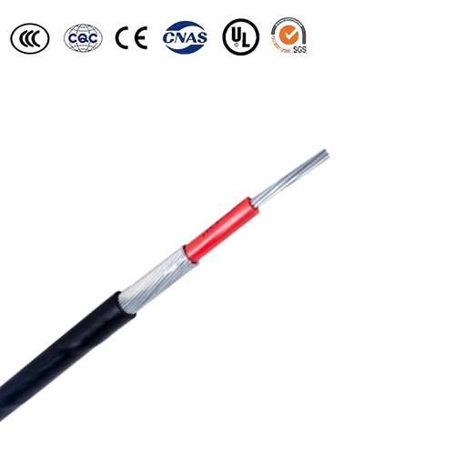
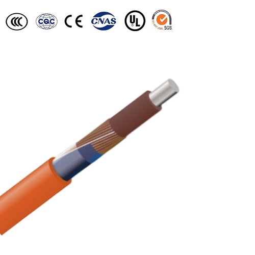
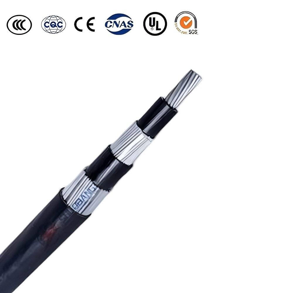
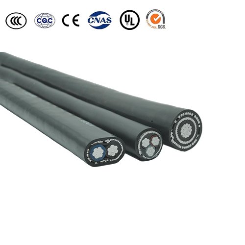
Copper Service Entrance (SE) Cable
Copper SE cable – premium choice for safe, high-efficiency service entrances.
Superior conductivity and performance for demanding residential loads.
Built with copper conductors for long-term durability and minimal voltage drop.
Ideal for underground or overhead entry – fire-rated and flexible.
Heavy-duty copper SE cable – trusted in commercial and high-end residential wiring.
Application
Copper Service Entrance (SE) Cable is engineered for reliable power delivery from utility connections to residential, commercial, and light industrial buildings. Featuring high-purity, annealed stranded copper conductors, this cable provides superior electrical conductivity, corrosion resistance, and excellent mechanical flexibility compared to aluminum counterparts.
The cable is insulated with durable PVC or sunlight-resistant thermoplastic jackets, designed to withstand outdoor exposure, moisture, and temperature variations. Copper SE cables are commonly available in two- or three-conductor configurations, including a bare or insulated copper ground wire for enhanced safety and fault protection.
Their robust design makes them suitable for service entrance wiring, panel feeders, and branch circuits requiring high reliability.
Copper SE cables are preferred where maximum conductivity, long-term durability, and minimal voltage drop are critical. Though typically more expensive than aluminum, copper cables deliver better performance in demanding environments and tighter installation spaces.
Specifications
| Category | Technical Description | Typical Applications |
|---|---|---|
| Cable Type | Service Entrance (SE) Cable with stranded copper conductors, designed to provide main power feed from utility meter to building panels | Ideal for residential, commercial, and industrial buildings requiring high reliability power distribution |
| Conductor Material | – High-purity annealed copper, Class B or C stranded for excellent conductivity and mechanical flexibility | Superior electrical conductivity and thermal performance compared to aluminum |
| Construction | – Multiple insulated copper conductors with color-coded insulation- Bare or insulated copper grounding conductor- Flame-retardant PVC sheath | Ensures robust mechanical protection and long service life |
| Insulation & Jacket | – Insulation typically XHHW-2 or THHN/THWN-2– Outer jacket: sunlight-resistant PVC or thermoplastic elastomer | Suitable for wet/dry locations, outdoor exposures, and conduit installations |
| Voltage Rating | Rated for 600 V, suitable for typical building distribution voltage levels | Complies with NEC and UL standards for service entrance cables |
| Standards Compliance | Meets UL 44, UL 1277, NEC Article 338, CSA C22.2, and ASTM specifications | Ensures safety, durability, and performance in demanding electrical environments |
Parameter
SER Two-Conductor Wih Bare Cotentric Ground (Formerly referred to as "Three Conductor")
| Conductor | Strandng | Nomnina 0.D.(MIs) | Allowable Ampacties | Approdimat e Net Weight Per 1000(Lbs) | Standard Package | ||||
| SizeConst, AWG or kcmil | Phase Conductor & Neutral | EquipmentGround Conduclor | 60℃ | 75℃ | 90℃ | Dwelling | |||
| 8-8-8-8 | 7 | – | 586 | 40 | 50 | 55 | – | 231 | B |
| 6-6-6 | 7 | – | 669 | 55 | 65 | 75 | – | 338 | B |
| 4-4-4 | 7 | – | 764 | 70 | 85 | 95 | 100 | 498 | B |
| 3-3-3 | 7 | – | 829 | 85 | 100 | 110 | 110 | 611 | B |
| 2-2-2 | 7 | – | 896 | 95 | 115 | 130 | 125 | 752 | B |
| 1-1-1 | 19 | – | 1021 | 110 | 130 | 150 | 150 | 948 | C |
| 1/0-1/0-1/0 | 19 | – | 1114 | 125 | 150 | 170 | 175 | 1169 | C |
| 2/0-2/0-2/0 | 19 | – | 1209 | 145 | 175 | 195 | 200 | 1444 | C |
| 3/0-3/0-3/0 | 19 | – | 1317 | 165 | 200 | 225 | 225 | 1792 | C |
| 4/0-4/0-4/0 | 19 | – | 1438 | 195 | 230 | 260 | 250 | 2226 | C |
| SER Three Conduclor With Bare Ground (Formerly relerred to as “Four Conductor”) | |||||||||
| 8-8-8-8 | 7 | 7 | 645 | 40 | 50 | 55 | – | 286 | B |
| 6-6-6-6 | 7 | 7 | 738 | 55 | 65 | 75 | – | 424 | B |
| 4-4-4-6 | 7 | 7 | 844 | 70 | 85 | 95 | 100 | 585 | B |
| 3-3-3-5 | 7 | 7 | 910 | 85 | 100 | 110 | 110 | 719 | B |
| 2-2-2-4 | 7 | 7 | 984 | 95 | 115 | 130 | 125 | 887 | B |
| 1-1-1-3 | 19 | 19 | 1132 | 110 | 130 | 150 | 150 | 1117 | C |
| 1/0-1/0-1/0-2 | 19 | 19 | 1235 | 125 | 150 | 170 | 175 | 1382 | C |
| 2/0-2/0-2/0-1 | 19 | 19 | 1342 | 145 | 175 | 195 | 200 | 1713 | C |
| 3/0-3/0-3/0-1/0 | 19 | 19 | 1462 | 165 | 175 | 195 | 225 | 2129 | C |
| 4/0-4/0-4/0-2/0 | 19 | 19 | 1598 | 195 | 230 | 260 | 250 | 2650 | C |
| Table values reflect XHHW-2 conductors | Package Codes: A-250′ B-500′ C- 1,000′ D-100′ E-150′ | ||||||||
| Alow able ampacities shown are for general use as specified by the National Electrical Code, 2011 Edition section 310.15 and 240.4(D). | |||||||||
| Unless the is marked for use at higher temperatures the conductor ampacities shall be limited to the following per NEC 110.14(C) | |||||||||
| 60 °C When terminated to equipment for circuits rated 100 amperes orless or marked for 14 – 1 AWG conductors. | |||||||||
| 75 ° C When terminated to equipment for circuits rated over 100 amperes or marked for conductors larger than 1 AWG. | |||||||||
| 90 °C XHHW wet or Dry locations for ampacity adjustment purposes using NEC section 310.1 5For dwelling ampacity use section 310.15(B)(7) | |||||||||
SEU Two Conductor With Bare Conentric Ground (Formerly relerred to as "Three Conductor")
| Conductor | Strandng | Nomnina 0.D.(MIs) | Allowable Ampacties | ApprodimateNet Weight Per 1000(Lbs) | Standard Package | ||||
| SizeConst, AWG or kcmil | Phase Conductor & Neutral | EquipmentGround Conduclor | 60℃ | 75℃ | 90℃ | Dwelling | |||
| 10-10-10 | 1 | 12 | 428×283 | 30 | 30 | 30 | – | 127 | ABC |
| 8-8-8 | 7 | 8 | 587×380 | 40 | 50 | 60 | – | 211 | ABC |
| 6-6-6 | 7 | 12 | 659×416 | 55 | 65 | 75 | – | 308 | BCE |
| 4-4-4 | 7 | 12 | 815×506 | 70 | 85 | 95 | 100 | 471 | BCE |
| 3-3-3 | 7 | 12 | 883×548 | 85 | 100 | 110 | 110 | 583 | B |
| 2-2-2 | 7 | 15 | 994×578 | 95 | 115 | 130 | 125 | 718 | BD |
| 1-1-1 | 19 | 14 | 1093×664 | 110 | 130 | 150 | 150 | 904 | B |
| 1/0-1/0-1/0 | 19 | 18 | 1179×707 | 125 | 150 | 170 | 175 | 1123 | BC |
| 2/0-2/0-2/0 | 19 | 18 | 1283×767 | 145 | 175 | 195 | 200 | 1379 | BC |
| 3/0-3/0-3/0 | 19 | 14 | 1429×862 | 165 | 200 | 225 | 225 | 1712 | BD |
| 4/0-4/0-4/0 | 19 | 18 | 1541×918 | 195 | 230 | 260 | 250 | 2146 | BC |
| SEU Two Conductor With Bare Conentric Ground(Formerly relerred to as “Three Conductor”)(Reduced Neutral) | |||||||||
| 6-6-8 | 7 | 8 | 659×416 | 55 | 65 | 75 | – | 281 | BC |
| 4-4-6 | 7 | 12 | 790×481 | 70 | 85 | 95 | 100 | 420 | BC |
| 3-3-5 | 7 | 15 | 843×508 | 85 | 100 | 110 | 110 | 515 | BC |
| 2-2-4 | 7 | 15 | 929×563 | 95 | 115 | 130 | 125 | 639 | BC |
| Table values reflect XHHW-2 conductors | Package Codes: A-250′ B-500′ C- 1,000′ D-100′ E-150′ | ||||||||
| Alow able ampacities shown are for general use as specified by the National Electrical Code, 2011 Edition section 310.15 and 240.4(D). | |||||||||
| Unless the is marked for use at higher temperatures the conductor ampacities shall be limited to the following per NEC 110.14(C) | |||||||||
| 60 °C When terminated to equipment for circuits rated 100 amperes orless or marked for 14 – 1 AWG conductors. | |||||||||
| 75 ° C When terminated to equipment for circuits rated over 100 amperes or marked for conductors larger than 1 AWG. | |||||||||
| 90 °C XHHW wet or Dry locations for ampacity adjustment purposes using NEC section 310.1 5For dwelling ampacity use section 310.15(B)(7) | |||||||||
PDF Download
PDF Download
WHY CHOOSE US
INOUIRY NOW
CONTACT US
PRODUCT CATEGORY
HOT-SALE PRODUCT
CNE cable solutions for industrial and commercial…
Factory-quality SNE cable meeting international …
Aluminum SE cable – trusted for residential service…